Pressure Control & Relief Valves
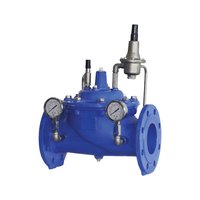
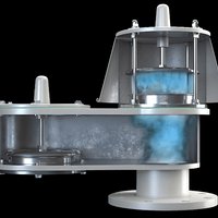
Safety and regulating valves that maintain system pressure or release overpressure.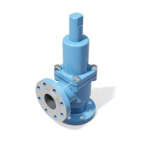

Spring-loaded pressure relief valves across 252 listed configurations — conventional and bellows types to API 526, orifice letters D through T (S excepted), in DN25, 40, 50, 80, 100, 150 and 200. Compare and submit an RFQ.
Sourcing at a Glance
- Standards / Certifications
- API 526, ASME Section VIII, API 520 (sizing)
Specifying Relief Valves: Relieving Case, Orifice, Back Pressure and Type
A relief valve is specified by calculation. Unlike an isolation valve, you cannot select one from a size and a class. The sequence is: identify the governing relieving scenario (fire case, blocked outlet, control-valve failure, thermal expansion), calculate the required relieving capacity, convert that to a required effective orifice area using API 520, then round up to the next standard orifice letter in API 526 and confirm the inlet and outlet ratings. A valve chosen on line size alone will be wrong in both directions — oversized valves chatter, undersized ones do not protect.
The API 526 orifice series. API 526 is a purchase specification: it fixes orifice designations D through T, spanning 0.110 to 26.0 square inches with the letter I omitted, along with valve size and pressure rating for inlet and outlet, materials, pressure-temperature limits and centre-to-face dimensions. That standardisation is the point — it lets valves from different manufacturers be interchanged on the same inlet-outlet combination. The catalogue lists orifices D, E, F, G, H, J, K, L, M, N, P, Q, R and T.
Conventional versus bellows. A conventional valve's bonnet is vented to the discharge side, so back pressure acts on the disc and shifts the effective set point. A bellows valve introduces a balancing bellows whose effective area equals the seat area, isolating the disc from back-pressure variation and holding set pressure in shared relief headers. Where several valves discharge into a common header, the bellows design is normally the correct one; where discharge is to atmosphere, conventional is simpler and cheaper.
Size, class and materials. DN25 to DN200 across 252 configurations, in ASME 150, 300 and 600, all spring-loaded and flanged. Bodies are A216 WCB, CF8M stainless and A352 LCB low-temperature carbon steel; trim is SS316 nozzle and disc. The −29 °C Charpy impact threshold is the conventional dividing line below which LCB replaces WCB.
Set pressure, accumulation and overpressure. Set pressure is normally at or below the protected equipment's maximum allowable working pressure under ASME Section VIII; the valve must then pass full rated capacity within the code-permitted accumulation above that pressure. These three figures — set pressure, allowable accumulation and required capacity — are what a supplier needs; the valve size falls out of them.
Back pressure in the enquiry. State both components: superimposed back pressure present in the header before the valve lifts, and built-up back pressure generated by the valve's own discharge through the outlet piping. Together they determine whether the conventional design's set-point shift is tolerable or a bellows valve is required.
Conformity. PED 2014/68/EU category and module with CE marking for the EU, SABER for Saudi Arabia, ECAS for the UAE, EN 10204 3.1 certificates as the procurement baseline, and NACE MR0175 for sour service. Where the protected equipment is code-stamped, state the code-stamp requirement explicitly at enquiry stage.
From spec to RFQ. Send: relieving scenario and required capacity, fluid and phase, relieving temperature, set pressure, superimposed and built-up back pressure, inlet and outlet line sizes and ratings, body and trim requirement, and destination market. Share the relief calculation or the datasheet with your RFQ and the orifice and configuration are confirmed against the catalogue directly.
How Relief Valves Work
Mechanism: a spring-loaded force balance that opens on overpressure and reseats on its own. A relief valve operates "on a simple force balance—upstream pressure pushes up on a disc seated against a nozzle, while a spring pushes down," and for as long as the spring wins, the disc stays seated and the valve is leak-tight. The moment that balance flips — pressure acting on the seat area exceeding the spring's preload — the disc lifts off the nozzle seat at what is called the cracking pressure, and "the valve will 'pop' open," with flow then controlled by the primary orifice rather than the narrow gap between the seating surfaces. Put more simply: "when the pressure of the line exceeds the set pressure, the disk starts to lift allowing the fluid to flow through the outlet and release pressure," and once enough has discharged to bring pressure back down, "the spring pushes back the disk in positive to close the valve preventing further release of fluid." The gap between the set (opening) pressure and the reseat pressure is called blowdown, and it is a controlled design feature, not a defect: "when the ring is moved upward, blowdown is increased (lowering the reseating pressure), and when it is moved downward, the blowdown is decreased."
Industries served: wherever a vessel, line or storage tank can be overpressured. Relief valves are "widely used in the chemical, petrochemical, power, and oil and gas industries," fitted not only to pressure vessels generally but to the "discharge sides of positive displacement pumps, compressors, and turbines," and to low-pressure storage tanks that need protection from vacuum as well as overpressure. The same source names refineries and large chemical plants specifically as environments where the hazard is not just mechanical failure but a toxic or flammable release — and steam plants rely on the identical spring-and-disc principle for boiler overpressure protection. The mechanical logic is the same in every one of these settings; what changes is the body material, orifice size and set pressure chosen against the specific vessel and fluid, which is why the catalogue is organised by orifice letter and pressure class rather than by end industry.
Standards landscape: a codified overpressure allowance, not a discretionary safety margin. Pressure-vessel regulation treats relief protection as mandatory rather than optional: US federal pressure-vessel rules covering the same overpressure-protection principle that ASME's vessel code embodies require that vessels "must be protected by pressure-relieving devices that will prevent the pressure from rising more than 10 percent above the maximum allowable working pressure," with a wider 20 percent allowance specifically where a device also has to cover fire exposure. API 526 sits alongside that percentage limit as the purchase specification that standardises how the valve meeting it is actually built and ordered — fixing the D-through-T orifice letters, inlet/outlet ratings and dimensions the catalogue lists — so the regulatory allowance and the physical valve a buyer specifies trace back to the same document chain. Sources: [Valve Magazine — Pressure Relief Valve Basics: Spring-Loaded Safety Relief Valves](https://valvemagazine.com/articles/pressure-relief-valve-basics-spring-loaded-safety-relief-valves/); [What Is Piping — Pressure Relief Valve](https://whatispiping.com/pressure-relief-valve/); [Cornell Law School LII — 46 CFR § 54.15-5](https://www.law.cornell.edu/cfr/text/46/54.15-5)
Frequently Asked Questions
- Conventional or bellows relief valve — which do I need?
- Choose by back pressure: conventional for atmospheric or dedicated discharge, bellows where back pressure varies. A conventional valve vents its bonnet to the discharge side, so any built-up or superimposed back pressure adds to the spring force and raises the effective set pressure — acceptable when the valve discharges to atmosphere or to a dedicated line. A bellows valve seals the disc area against back-pressure variation with a balancing bellows, holding set pressure in shared or variable discharge headers. Both are listed catalogue types. State the discharge arrangement and expected back pressure — that is the deciding input.
- How do I pick the orifice letter?
- You do not pick it directly — you calculate the required effective orifice area for the governing relieving case using API 520, then select the next larger standard orifice from the API 526 letter series. API 526 defines designations D through T spanning 0.110 to 26.0 square inches (the letter I is omitted to avoid confusion with the numeral 1), which is what makes valves from different makers interchangeable on the same inlet and outlet ratings. The catalogue lists D through T excluding S. Send the relieving case, not the desired orifice, with your RFQ.
- What is the difference between set pressure and back pressure?
- Set pressure is the inlet gauge pressure at which the valve is adjusted to open — normally at or below the vessel's maximum allowable working pressure under ASME Section VIII. Back pressure is the pressure at the outlet: superimposed back pressure exists in the discharge header before the valve opens, while built-up back pressure develops from the valve's own flow through the discharge piping. Both figures belong in the enquiry, since together they decide whether a conventional or bellows design is appropriate.
- Which body and trim materials are available?
- Listed bodies are carbon steel (A216 WCB) for general service, SS316 (CF8M) for corrosive media, and low-temperature carbon steel (A352 LCB) for cold service — below roughly −29 °C, the conventional Charpy impact threshold, low-temperature grades replace standard carbon steel. Trim across the listed range is SS316 nozzle and disc. State the relieving fluid, its temperature and any corrosive or sour-service condition in the enquiry.
- What conformity and certification applies?
- Catalogue relief valves reference API 526 for dimensional and material specification together with ASME Section VIII for pressure-vessel code compliance. For export, EU-bound equipment is categorised under PED 2014/68/EU with CE marking per the applicable module; Saudi imports require SABER; UAE imports require ECAS; EN 10204 3.1 material certificates are the EU procurement baseline. State the destination market and whether code stamping is required at enquiry stage.