• Homeβ€Ί
  • Flush Bottom Valves
  • Homeβ€Ί
  • Valvesβ€Ί
  • Flush Bottom Valves
  • Flush Bottom Valves

    Source flush bottom valves from India's verified manufacturers and exporters on Himalay. Browse the full range for industrial and export applications.

    Showing 1 items
    1 items
    operation type
    Handwheel
    Pneumatic Actuator
    body material
    SS304
    SS316
    WCB
    end connection
    Bottom Mount
    Flanged
    seat material
    Metal
    PTFE
    trim material
    SS316
    Flush Bottom Valves sourcing

    About Flush Bottom Valves

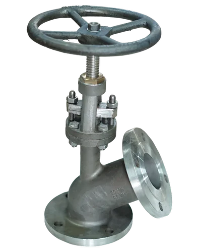
    Flush bottom valves for reactor and tank discharge in disc-lift and piston designs, flanged DN25 to DN200, in stainless steel, alloy 20, Hastelloy and PTFE-lined builds.

    A flush bottom valve, also called a flush bottom tank valve or ram-type bottom outlet valve, mounts directly on the lowest point of a reactor, vessel or storage tank so the vessel drains completely with no stagnant pocket between vessel and valve. The seat is machined so that the closure member sits flush with, or protrudes into, the vessel bottom: disc-type designs raise or lower a contoured disc against a seat at the vessel pad, while piston (ram) type designs drive a plunger up into the vessel, breaking through settled solids or crystallised product to open a blocked outlet. Valves are supplied with Y-type angled bodies (typically discharging at 45 or 60 degrees) or straight-through bottom entry, flanged to ASME B16.5 or DIN patterns, in sizes DN25 to DN200 and ratings to Class 150/300 with ASME B16.34 materials practice and API 598 testing where specified. Materials follow the process: CF8M/316 stainless as the baseline, alloy 20, Hastelloy and other nickel alloys for aggressive chemistry, PTFE/PFA-lined carbon steel for corrosive duties at moderate temperatures, and jacketed bodies for products that must stay hot to flow. Operation is handwheel, gear or pneumatic actuator. When enquiring, state vessel pad size and flange drilling, discharge angle and line size, whether the closure must open upward into the vessel or downward, process fluid and solids behaviour, temperature, jacketing, materials and quantity.

    Buyer guide

    Specifying Flush Bottom Valves: Type, Opening Direction and Materials

    01

    What the valve is actually for

    Any ordinary valve piped below a reactor leaves a nozzle-length column of product between vessel and seat β€” a dead pocket that will not drain, will not mix, and in a reactor will foul, freeze or react on its own. A flush bottom valve eliminates that pocket by putting its seat at the vessel wall itself, so the vessel drains to the last usable litre and the batch has no stagnant heel. It is a vessel component as much as a valve, which is why the specification starts from the vessel drawing.

    02

    Disc versus ram

    Disc-lift designs stroke a contoured disc a short distance off a seat machined into the pad region; they are compact, lower cost, and right for clean liquids, solvents and light slurries. Ram (piston) designs stroke a plunger through the seat and up into the vessel, using the stroke itself to break crusts, compacted solids and crystallised product β€” the standard answer for sugar, resin, agrochemical and API reactors where the bottom outlet cakes between batches. Ram valves need more headroom below the vessel for the actuator and a check on agitator clearance above the pad.

    03

    Opening direction

    Upward opening self-cleans the seat and gains sealing help from vessel pressure but intrudes into the batch; downward opening keeps the batch undisturbed but relies on the product not bridging. Fouling service favours upward; clean storage favours downward. Decide this consciously β€” it is the single most argued-over detail in flush bottom procurement.

    04

    Body patterns and connections

    Y-pattern bodies discharge at 45 or 60 degrees to clear vessel skirts and structural steel; straight patterns drop vertically. Inlet flanges DN25 to DN200 drilled to ASME B16.5 Class 150/300 or DIN PN16/PN40, matching the vessel pad. Confirm face finish and gasket type against the vessel design.

    05

    Materials, linings and jackets

    CF8M is the baseline; alloy 20, Hastelloy C-276, Monel and duplex grades serve aggressive chemistry; PTFE/PFA-lined bodies and discs cover broad corrosion at moderate temperatures. Limpet or full jackets on body and branch keep molten or viscous products mobile β€” state the heating medium, jacket pressure and whether the disc itself must be heated. Stem packing PTFE or graphite per temperature.

    06

    Standards and testing

    There is no dedicated flush bottom product standard; pressure boundary practice follows ASME B16.34, flanges ASME B16.5, and shell and seat testing API 598 where the purchaser specifies formal testing. Vessels under pressure regulations may additionally require material certificates to EN 10204 3.1 β€” ask for them at enquiry, not after.

    07

    Actuation

    Handwheels serve occasional draining; gear operators larger sizes; pneumatic cylinders with spring action (usually fail-closed), solenoid voltage and limit switches serve batch automation.

    What to state in the enquiry

    Vessel pad details, type and opening direction, sizes and angle, materials or lining, jacketing, process conditions including vacuum and cleaning cycles, actuation, testing and certification, quantity. Indian manufacturers build flush bottom valves for pharma, agrochemical and dye industries as a specialty and export with full documentation.

    Submit an enquiry β†’
    Technical guide

    How Flush Bottom Valves Work

    Geometry does most of the work

    The defining feature of a flush bottom valve is where sealing happens: at the plane of the vessel's bottom pad, not a nozzle-length away. The seat ring is machined so its sealing surface is continuous with the vessel interior, and the closure β€” disc or ram nose β€” completes the vessel wall when shut. There is therefore no product column standing in a cold nozzle between batches: the batch's last litre rests on the valve itself, stirred and heated with the rest of the vessel contents. Everything else in the design is arranged around preserving that geometry under thermal cycling, corrosion and mechanical abuse.

    The stroke as a tool

    In a ram-type valve the stroke is deliberately long enough to carry the plunger nose past the seat and into the vessel. That motion shears off any cake bonded across the outlet β€” crystallised product, settled catalyst, polymer skin β€” using actuator force rather than an operator's rod and a shutdown. The plunger's contour matters: a conical nose wedges through deposits and centres itself on closing; a flat-faced disc presents a cleanable surface but clears less aggressively. On closing, the nose swages remaining solids aside and lands on the seat; quality designs give the seat a slight interference or a renewable seat ring because this closing action is exactly where wear concentrates.

    Sealing forces and direction

    With upward opening, vessel pressure acts on top of the closure and adds to seating force β€” the valve gets tighter as the batch pressurises, and the failure direction under actuator loss is closed if a spring is fitted. With downward opening, vessel pressure works to lift the disc off its seat, so spring and actuator sizing must overcome full hydrostatic and process pressure across the seat area; underestimating a tall liquid column here is a classic sizing error. This mechanical asymmetry, more than cleaning behaviour, is why pressurised reactors usually take upward-opening rams.

    Thermal behaviour and jackets

    Products chosen for flush bottom discharge are often the ones that solidify: molten sulphur, resins, waxes, saturated solutions. A jacketed body keeps the discharge path above the melt point, but the disc and the short seat zone are the coldest points in the system because they face ambient through the stem. Designs answer with jacketed branches, extended jackets around the seat area, and occasionally heated plungers; the buyer's part is stating the melt or crystallisation temperature and the heating medium honestly so the maker can prove heat reaches the seat.

    Failure modes

    The recurring ones: seat and nose galling from closing onto hard crystals (specify hardfaced or renewable seats for crystallising duties); packing leakage from thermal cycling and stem side-loads (live-loaded or bellows-sealed stems are available); liner collapse in PTFE-lined valves under vessel vacuum steps (declare vacuum in the datasheet); agitator strikes on upward-opening plungers when clearances were never checked; and actuators that cannot break a fully caked outlet after an extended shutdown (state the worst-case condition, not the normal one, for actuator sizing).

    Why detail matters here

    A flush bottom valve is semi-custom: pad size, angle, stroke, lining and jacket interact, and two valves with the same nominal size can be non-interchangeable. Precise enquiry data β€” ideally the vessel bottom drawing β€” is what turns a quotation into the right valve.

    Popular searches in Flush Bottom Valves

    Frequently Asked Questions

    Disc-type or piston (ram) type β€” which flush bottom valve should I choose?
    Should the disc open into the vessel or away from it?
    What materials and linings are typical for corrosive reactor duty?
    What should my flush bottom valve RFQ include?